There was a time while I went to school when I lived and breathed electronic projects. I got a degree and then spent the subsequent years doing absolutely nothing with it and forgetting most of what I learned.
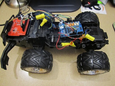
Enjoyably, over the last year I’ve been exposed to a series of iPhone electronics projects through the wonderful iPhone & iPad Electronics Projects book by Mike Westerfield. By far my favorite project in the book has been hacking an RC car to control it with my iPhone. I stole my daughter’s RC car (she wasn’t using it, don’t judge me), took it apart, ripped out the electronics, and replaced them with a new control mechanism. Here is a demonstration of the result.
I have no interest in detailing all the steps involved in the project. You can read Mike’s book to get that. Instead, I’ll give a high level description of what is involved and mention what is different in my implementation from what is in the book.
The New Face of Hobby Electronics
Like I said, I haven’t wired up anything in, gosh, over 15 years (makes me feel old). Apparently no one is using the old IC gates I used to design with, which is a little unsettling (although I presume 15 years before that you used independent transistor components to build gates, so I guess it’s only a matter of time).
Apparently the big thing now is Arduino hardware. An Arduino is a microcontroller attached to a small board with the associated electronics that enable USB connections to computers as well as digital and analog inputs and outputs to interface with other electronics such as sensors and motor controllers. Despite my nostalgic whining this is actually a pretty good development for me. I’m personally much better at programming microcontrollers than designing digital electronics.
Arduinos also have a convenient pin-out configuration that allows you to stack on auxiliary boards called shields that provide pre-packaged electronics (or you can get blank shields on which you solder your own electronics). The iPhone car uses an Arduino with two shields: a Bluetooth low energy shield for communication and a motor controller shield for power.
Insert “Scotty” Joke About More Power Here
Mike’s book has lots of clear and helpful instructions on choosing an appropriate car and checking the power requirements to the motors. I, of course, chose to ignore all that and hook up what I had. It turns out that the H-bridge circuit described in the book doesn’t provide enough current to run my car’s drive motor. (But I sure got that H-bridge to heat up. I’m surprised I didn’t smoke it.)
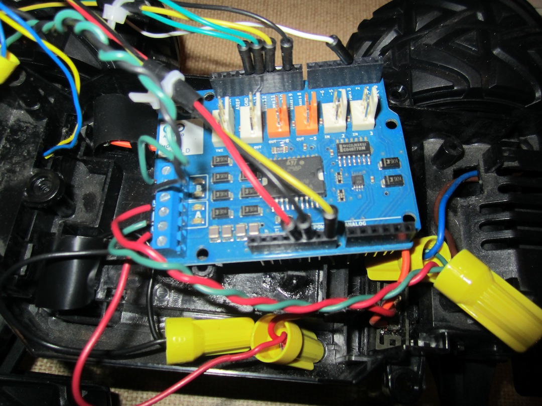
I subsequently went to Radio Shack to see if I could find anything helpful. It turns out Radio Shack now sells quite a bit of Arduinos and equipment, and I got a great deal on a prefabricated motor shield with twice the amperage rating as my previous circuit.

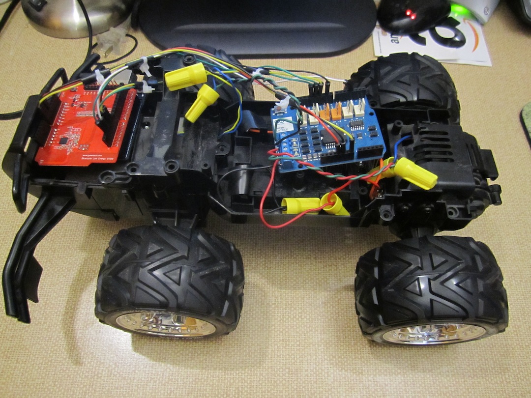
Here is where the fun starts with the project. You crack open the case of the RC car to get at that little piece of electronics controlling everything. Now rip that sucker out of the car. There are 6 wires that you need to cut: two to the battery, two to a motor that turns the front wheels, and two to the driver motor that spins the back wheels. There is also a seventh wire for the antenna. It might be just a loose wire or it might be connected to some metal on the chassis, but either way you don’t need it. My Arduino motor shield (shown here) comes with a nice screw terminal that makes it easy to attach the leads to both motors and the power source (battery).
Speaking of power supply, you are actually supposed to have two power sources: one to power the Arduino and one to power the motors. Mike’s book suggests replacing the power switch with a double pole switch for both sources. I’m way too lazy for that crap. Instead, I just hooked up the battery that comes with the RC car to power everything.
This is stupid for two reasons. First, the battery is rated for 6V, which is well below the suggested 7V supply for the Arduino’s voltage regulator. It shouldn’t turn on at all. Even if it does turn on, when the driver motor first turns on, it’s going to create a spike in current draw that will divert power away from the Arduino and shut it off.
But despite all that, it still works. It turns out that a freshly charged battery actually supplies about 6.5V, which seems to be enough. Also, between the current capabilities of the battery and whatever capacitance is built into the motor control, the power draw from the motors does not seem to effect the voltage significantly.
So I guess being stupid and lazy isn’t so bad after all.
Red Bears and Blue Teeth

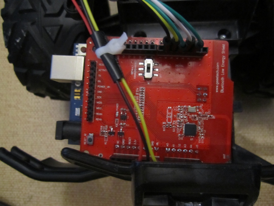
The next thing we need is a way to interface our electronics with an iPhone, and that’s where our second shield comes in. For this we use a RedBearLabs Bluetooth low energy shield, shown here. You’ll notice that the Bluetooth low energy shield is attached directly to the Arduino whereas the motor shield is attached by a bunch of jumper wires. This is because the two shields have conflicting pin arrangements. (It took me hours to diagnose this simple problem. Apparently part of the Arduino specification is to provide crappy documentation.) The jumper wires permute the pins from those not used by the Bluetooth low energy shield to the inputs of the motor shield.
That brings us to the program on the iPhone to interface with the Arduino and control the car. As specified in Mike’s book, I use the techBASIC application, which interprets BASIC scripts and allows you to interface with the Bluetooth low energy hardware on the iPhone. techBASIC comes with all the programs outlined in Mike’s book, including one to control the car. However, I made some changes to the program for a variety of reasons.
- Mike’s circuit for the motor control connects the input signals directly to the gates driving the motors. The motor shield adds a bit of logic to make enable and direction controls, which are different.
- Mike’s program uses timers within techBASIC to send a pulse width modulation signal to the car to adjust the speed. I discovered that the Arduino is capable of automatically creating a pulse width modulation signal, so I stripped out that part of the program and just sent a number to the Arduino.
- Mike’s program has a clever interface that uses the accelerometers in the iPhone to control the direction of the car. You tilt the iPhone in a certain direction and the car goes in that direction. As neat as that interface is, I find it extraordinarily frustrating. Thus, I created my own interface that uses the position of your finger on the touchscreen to control the direction.
Final Remarks
There is something rousing about watching a physical device like an RC car under the control of the all-purpose, portable, tricorder-like device, and it’s been a really fun project. That’s good, because ultimately this project has no practical value. In essence, I ripped out a control board that probably costs the manufacturer about $1 and replaced it with about $75 worth of home electronics and interfaced it with an iOS device that costs $400 at a minimum. And despite the fancy interface, it cannot compete with the tactile feedback of the original remote control or the stability of the original radio signal.
But, of course, none of that is the point. The point is, in the immortal words of Butt-head, “Uh huh, huh huh. Cool.”